Peerless Tips About How To Connect Two Resistors In Parallel

Understanding Parallel Resistors
1. Why Parallel? Let's Get to the Point.
Ever wondered why electrical engineers and hobbyists alike rave about parallel resistor configurations? Well, it's not just because they look pretty (though a well-arranged circuit can be a thing of beauty!). The real magic lies in how parallel resistors affect the overall resistance of a circuit. Instead of increasing resistance like resistors in series, connecting them in parallel decreases the total resistance. Think of it like opening up more lanes on a highway; more current can flow through, leading to lower overall impedance.
Imagine you have a circuit that's drawing too much current. Slapping a resistor in there can help, but what if you don't want to increase the resistance too much? That's where parallel resistors shine. They let you fine-tune the resistance, offering a sweet spot between protecting your components and maintaining optimal performance. Plus, it's a fantastic way to distribute the heat load across multiple resistors, preventing any one component from getting too toasty.
Another compelling reason for using parallel resistors is redundancy. If one resistor decides to take an early retirement (burn out), the circuit can still function, albeit with a slightly different resistance. This is crucial in critical applications where downtime isn't an option, like in certain industrial control systems or even medical equipment. It's like having a backup generator — you hope you never need it, but you're sure glad it's there!
So, in a nutshell, connecting resistors in parallel gives you more control over the circuit's total resistance, offers a way to manage heat, and provides an element of fault tolerance. Sounds pretty good, right? Let's dive into exactly how to connect two resistors in parallel.

The "How-To"
2. The Connection Process
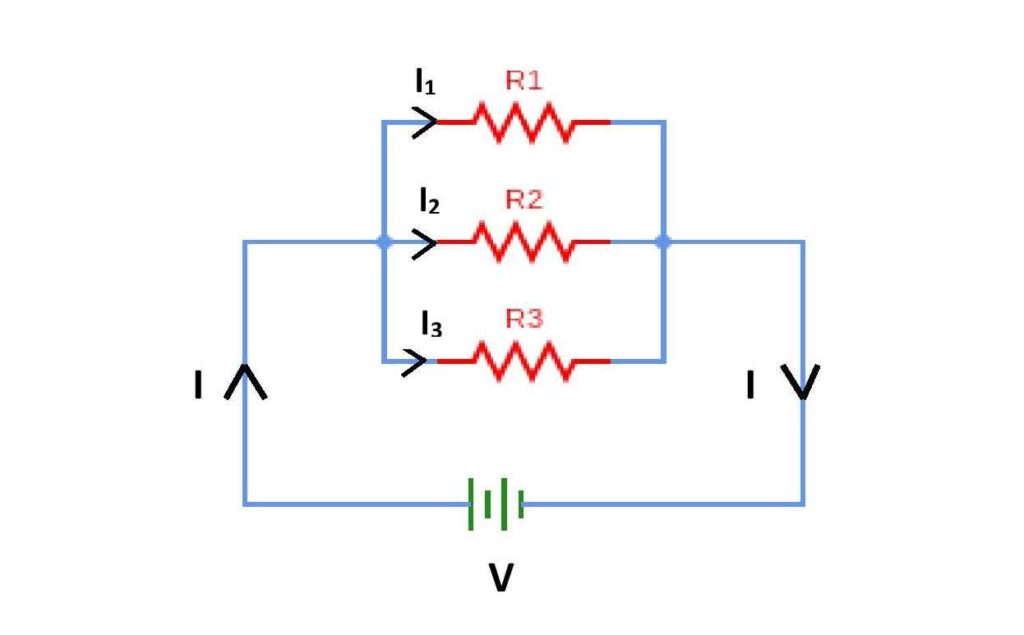
Alright, let's get our hands dirty (metaphorically speaking, of course! Cleanliness is next to godliness, especially when dealing with electronics). Connecting two resistors in parallel is surprisingly straightforward. The key concept is to connect both ends of each resistor together. Think of it like holding hands; each resistor has two "hands," and you're making them hold each other's hands. Seriously, that's basically it!
Here's a step-by-step breakdown:
- Identify your resistors: Make sure you know the resistance value of each resistor you are going to connect. This information is typically indicated on the resistor itself, using color bands (resistor color code) or printed with a number.
- Find a suitable connection point: Now, find an open circuit board or use breadboard, and insert the first resistor on it.
- Connect Resistor 2: Insert the second resistor so that its legs are directly aligned with the first resistor's legs. This means that one leg of resistor 2 must sit right alongside one leg of resistor 1, and the other leg of resistor 2 must sit right alongside the other leg of resistor 1.
- Ensure Secure Connections: This depends on your method of connection. If you're using a breadboard, make sure the resistor leads are firmly seated in the breadboard holes. If you're soldering, make sure the solder joints are shiny and smooth. A dull, lumpy solder joint is a sign of a cold solder joint, which can lead to unreliable connections.
That's really all there is to it! It's so simple, even your grandma could do it (assuming your grandma is electrically inclined, of course!). The important thing to remember is that both ends of each resistor need to be connected together. If you only connect one end, you've essentially just created a fancy-looking open circuit.
Pro Tip: Before you start soldering or permanently connecting anything, it's always a good idea to double-check your connections with a multimeter. Set it to measure resistance and verify that the total resistance is what you expect (we'll get to calculating that in the next section). A quick check can save you a lot of headaches down the road.

Calculating the Total Resistance
3. The Formula
Okay, time for a little math, but don't run away screaming! Calculating the total resistance of two resistors in parallel is actually quite simple. The formula looks a bit intimidating at first, but once you understand it, you'll be whipping out answers like a seasoned pro.
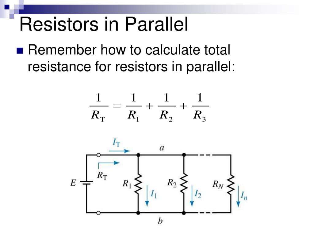
The formula for calculating the total resistance (Rtotal) of two resistors (R1 and R2) in parallel is:
1 / Rtotal = (1 / R1) + (1 / R2)
To find Rtotal, you'll need to take the reciprocal of the result. This essentially means that Rtotal = 1 / ((1 / R1) + (1 / R2)).
Let's break it down with an example. Suppose you have a 100-ohm resistor and a 200-ohm resistor connected in parallel. Using the formula:
1 / Rtotal = (1 / 100) + (1 / 200) = 0.01 + 0.005 = 0.015
Rtotal = 1 / 0.015 = 66.67 ohms (approximately)
As you can see, the total resistance is lower than either of the individual resistors. This is always the case when resistors are connected in parallel. The combined resistance will always be less than the smallest resistance value in the parallel circuit.
There's also a handy shortcut formula you can use specifically for two resistors in parallel:
Rtotal = (R1 R2) / (R1 + R2)
Using the same example: Rtotal = (100 200) / (100 + 200) = 20000 / 300 = 66.67 ohms. See? The same answer, just a different path!

Practical Applications
4. Beyond the Theory
Now that you know how to connect resistors in parallel and calculate the total resistance, let's talk about where you might actually use this knowledge in the real world. The applications are surprisingly diverse, spanning everything from hobby electronics projects to complex industrial systems. Parallel resistors pop up wherever the ability to precisely control resistance, manage heat, or provide redundancy is needed.
One common application is in LED circuits. LEDs require a specific amount of current to operate efficiently, and resistors are often used to limit that current. Connecting multiple LEDs in parallel, each with its own current-limiting resistor, can be a great way to create a bright and evenly lit display. The parallel resistors ensure that each LED receives the correct amount of current, preventing them from burning out prematurely.
Another area where parallel resistors are frequently used is in voltage dividers. A voltage divider is a simple circuit that reduces a voltage to a lower level. By using a combination of series and parallel resistors, you can create a voltage divider that provides a very specific output voltage. This is particularly useful in applications where you need to interface a high-voltage circuit with a low-voltage circuit, such as when connecting a sensor to a microcontroller.
High-power applications also benefit from parallel resistors. When dealing with circuits that dissipate a lot of power, individual resistors can overheat and fail. By using multiple resistors in parallel, you can distribute the heat load across a larger surface area, preventing any one resistor from getting too hot. This is common in power supplies, motor controllers, and other high-current circuits.

Wiring 2 Resistors In Parallel At Matthew Kathryn Blog
Troubleshooting
5. Solving Common Issues
Even with something as simple as connecting two resistors in parallel, things can sometimes go wrong. Here are a few common issues you might encounter, along with some tips on how to troubleshoot them:
Incorrect Resistance Value: Double-check the resistor values using a multimeter to be 100% sure. Resistor color codes can sometimes be confusing, especially in low lighting, so verifying with a multimeter is always a good idea.
Bad Connections: As mentioned earlier, a bad connection can wreak havoc on your circuit. If you're using a breadboard, make sure the resistor leads are firmly seated in the holes. If you're soldering, inspect the solder joints for any signs of cold solder joints (dull, lumpy appearance). Reflow the solder if necessary to ensure a good connection.
Unexpected Readings: If your multimeter is showing an unexpected resistance value, the first thing to do is to disconnect the power supply. Sometimes, other components in the circuit can influence the resistance reading. Disconnecting the power will isolate the parallel resistor combination and give you a more accurate reading.
Overheating Resistors: If you notice that your resistors are getting excessively hot, it's a sign that they're dissipating too much power. This could be due to an incorrect resistor value, a higher-than-expected voltage, or a faulty component elsewhere in the circuit. Check the resistor's power rating and make sure it's sufficient for the application. Consider using higher-wattage resistors or adding more resistors in parallel to distribute the heat load.

Circuit Diagram Parallel Resistors
FAQ
6. All You Need to Know
Still have some questions buzzing around your brain? Here are some frequently asked questions to help clear things up:
Q: What happens if I use resistors with drastically different values in parallel?
A: The total resistance will be closer to the value of the smaller resistor. The smaller resistor "dominates" the parallel combination, providing the path of least resistance for the current.
Q: Can I connect more than two resistors in parallel?
A: Absolutely! The same principles apply to any number of resistors in parallel. The formula for calculating the total resistance becomes 1/Rtotal = (1/R1) + (1/R2) + (1/R3) + ... and so on.
Q: What if one of the resistors in parallel burns out?
A: The total resistance of the circuit will increase, as the burned-out resistor effectively becomes an open circuit. The circuit will still function, but the current distribution and overall performance may be affected. This is why parallel resistors are sometimes used for redundancy in critical applications.